4-Zone Fermentation Controller
A mains-switching brewery controller designed as a real, manufacturable product. ESP32-S3, four triac heater zones and four relay pump zones, 288 parts on a 4-layer board. Taken from written brief to routed PCB in three days, with AI agents driving KiCad.
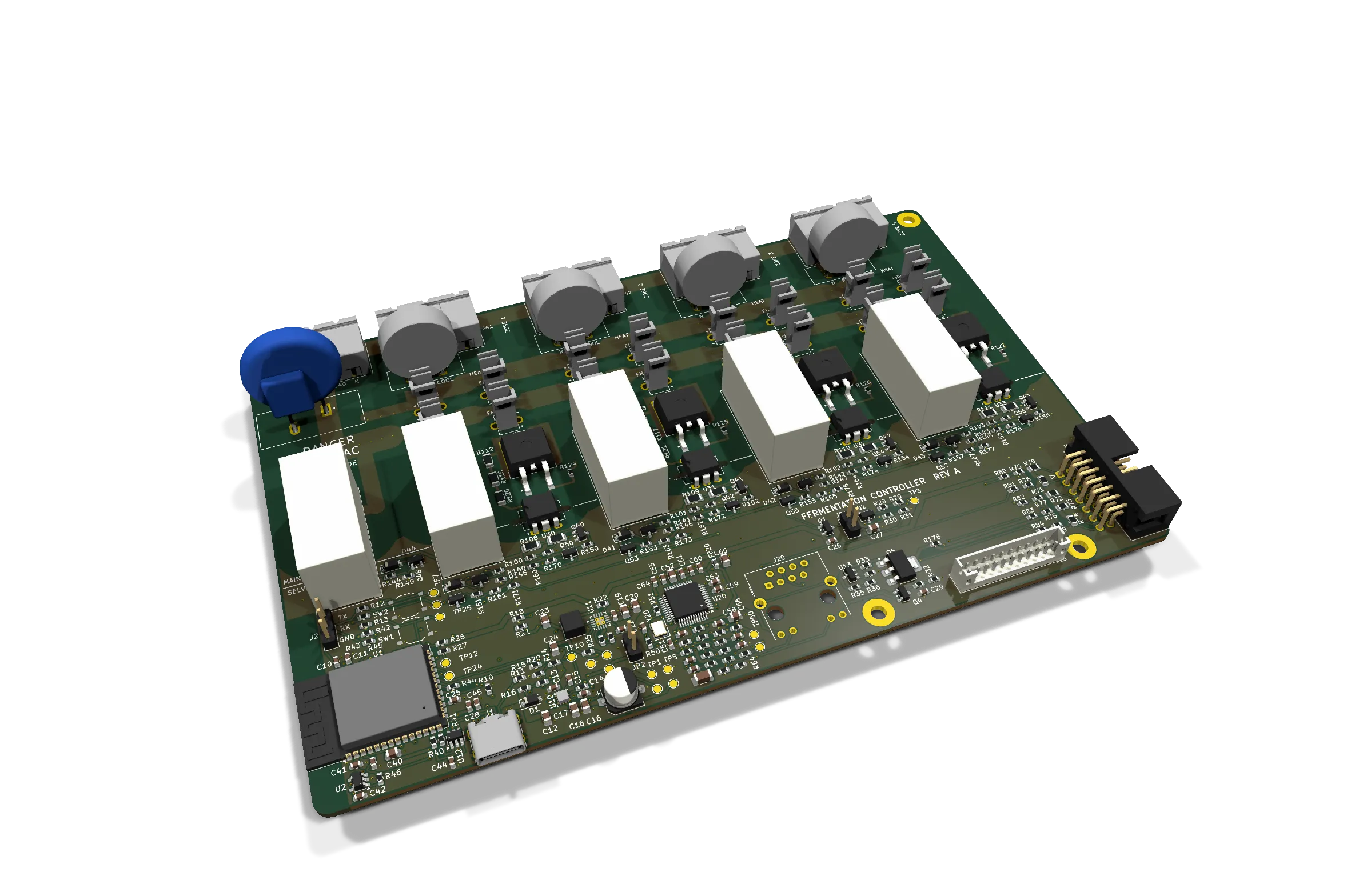
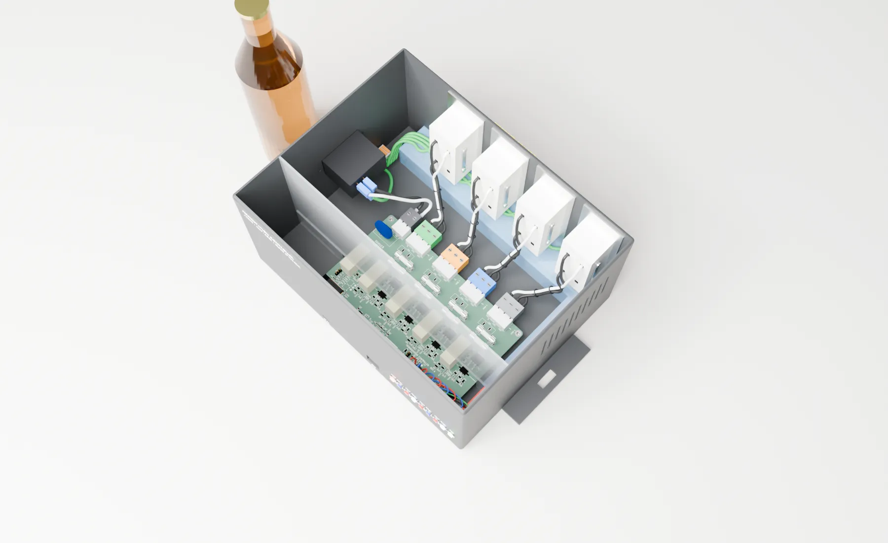
The brief was one sentence of intent and a lot of constraints: a real, manufacturable product. Schematic, PCB, BOM, fab outputs, a printable enclosure and production firmware for a four-fermenter home brewery. Each zone gets a temperature sensor, a heater and a glycol pump, plus a fifth sensor for the glycol reservoir. The low-voltage side is powered from USB-C only; the 120 VAC side switches load power through an IEC inlet to NEMA receptacles.
It isn’t UL-listed and never will be, so the design goal is simple to state and hard to meet: fail safe, stay in the box. Bring-up, surge testing and firmware are still ahead.
Five layers of fail-safe OFF
The most important finding came before any schematic: an ESP32-S3 panic reboot resets the CPUs but not the GPIO matrix. An output that was on stays on through the crash. So heaters are off by five independent means:
- 10 kΩ gate pull-downs on every driver.
- An ARM rail, a P-FET that is off by default, feeding every relay coil and optotriac LED.
- A bootloader hook that forces the output pins low before anything else runs.
- An external TPS3823 watchdog on EN, kicked from the control loop and never from a timer.
- A heater master relay in series with the heater bus, against a shorted triac.
A charge-pump ARM driven by the LEDC peripheral was rejected, because LEDC survives the reset too. The master relay covers heaters only: a welded pump relay over-cools, which loses beer but isn’t a hazard.
Mains design decisions
- 800 V semiconductors on a 120 V line. A 275 VAC MOV clamps around 710 V, above what 600 V parts survive. A stress review later showed a 2.5 kV surge puts about 1.23 kV across the off-state parts, which moved the design to a thermally protected MOV and removed the snubber footprints (a fitted snubber would dump 31.5 A into the triac during a surge).
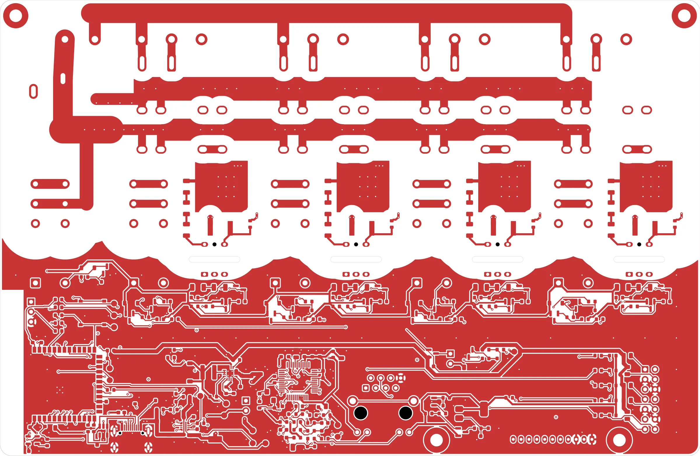
- Size copper to the fuse that protects it, not to the load. The inlet fuse came down from 10 A to T4A based on real loads, and every mains conductor is sized to ≤10 K rise with IPC-2152’s conservative method. A script cuts a cross-section across every mains conductor every 0.5 mm to prove it.
- Isolation as data. 8 mm creepage target, 6.4 mm absolute minimum, 12.8 mm relay coil-to-contact. A barrier-check script proved 48 all-mains nets and zero crossings. A DRC “canary” plants a deliberate violation to prove the custom rules are actually live.
- Constraints before copper. A net inventory, the fab house’s named stack-up, and a small 2D field solver (checked against Hammerstad-Jensen) set trace geometry before routing: 90.3 Ω for USB and 99.4 Ω for Ethernet.
How AI was used
This project is the clearest example of my method:
- Phase gates. Architecture, component selection, schematic, placement, routing. At every gate the agent stops, summarizes decisions and open risks, and waits for my approval. Placement renders are approved before a single trace is routed.
- A decision log. D-001 to D-043, each with the alternatives considered, the evidence and who accepted it. When a later phase contradicts an earlier decision, the log catches it.
- Tools with defined roles. One KiCad MCP server is the only writer of design files; a second is locked read-only as a reviewer;
kicad-cliwins any disagreement. Each schematic sheet is drawn by a script, and a netlist comparison proves every redraw is electrically identical to the one before. - Parallel reviewer agents. Four read-only reviewers (mains stress, low-voltage stress, and a pin-out check on each side) ran 281 checks. Their findings changed the design three times, including replacing a zener crowbar that could trip on a healthy rail with a TL431-and-SCR trigger.
- Parts rigor. A part is final only after a live distributor API lookup. Anything unconfirmed is marked UNVERIFIED wherever it’s used.
The honest lesson, written into the log after the mains buses were found undersized post-routing: check every accepted constraint from earlier phases against the finished layout before calling a phase done. Agents are fast; gates are what make fast safe.